Yolo Amateur Radio Society
Serving Yolo County, California
Serving Yolo County, California
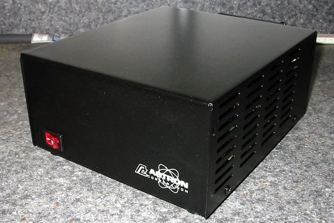
Astron SS-30 power supply - adding Anderson PowerPoles
by Robert Schulz KC6UDSI've done three of these conversions now, and it works very well. You keep the stock setscrew power connectors, and add four Anderson PowerPole connections. As with all projects of this sort, consider yourself warned that you do this at your own risk, it probably voids the warranty, it could cause damage to the power supply, the equipment attached to the power supply, and surrounding property, and all sorts of other disclaimer-type warnings. So: You Have Been Warned! Here is a picture of the power supply: Astron SS-30 Power Supply:A slightly modified version of this article, with some helpful editorial comments, can be found on the Repeater Builder's Technical Information Page.
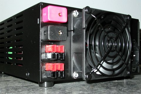
 If you look on the back, below the stock power connections, you will see two knockouts, obviously intended for a second pair of the setscrew connectors (sorry, the picture is a touch blurry):
Rear of power supply showing knockout locations:
If you look on the back, below the stock power connections, you will see two knockouts, obviously intended for a second pair of the setscrew connectors (sorry, the picture is a touch blurry):
Rear of power supply showing knockout locations: 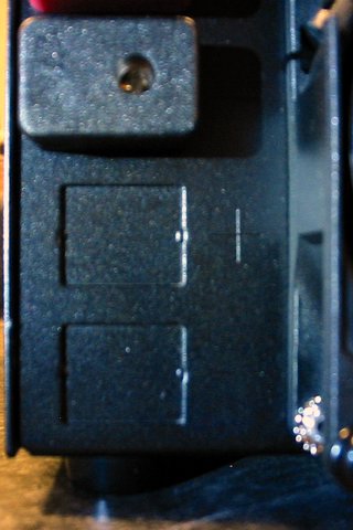 Removing the cover (you have the power supply unplugged, right?), here is the inside view:
Power supply with cover removed showing knockouts from the inside:
Removing the cover (you have the power supply unplugged, right?), here is the inside view:
Power supply with cover removed showing knockouts from the inside: 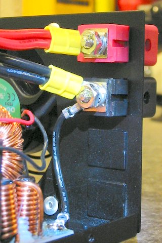 The first step is to remove the knockouts. I haven't figured out the best way of doing this yet - I've used pliers, a screwdriver and hammer, and this time, a C-clamp. Your goal is to remove the knockouts without bending the back panel of the power supply. If you look carefully, you can see that there won't be a lot of metal there when you remove the knockouts. I worked the C-clamp gently back-and-forth until the knockouts snapped out. It took a little patience, and I slightly bent the panel, but was able to bend it back into shape. (again, picture is a little blurry):
Knocking out a knockout:
The first step is to remove the knockouts. I haven't figured out the best way of doing this yet - I've used pliers, a screwdriver and hammer, and this time, a C-clamp. Your goal is to remove the knockouts without bending the back panel of the power supply. If you look carefully, you can see that there won't be a lot of metal there when you remove the knockouts. I worked the C-clamp gently back-and-forth until the knockouts snapped out. It took a little patience, and I slightly bent the panel, but was able to bend it back into shape. (again, picture is a little blurry):
Knocking out a knockout: 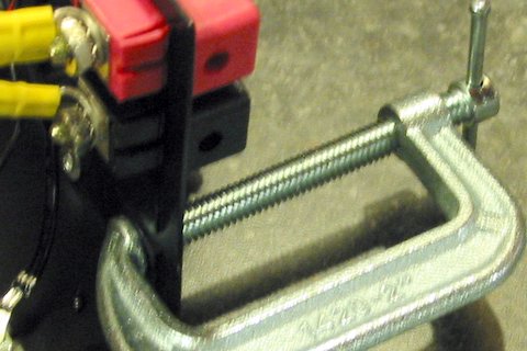 When you remove the knockouts, KEEP THEM! You will use the little metal rectangles as spacers later in the installation. Here is a picture with the knockouts removed:
Knockouts knocked out:
When you remove the knockouts, KEEP THEM! You will use the little metal rectangles as spacers later in the installation. Here is a picture with the knockouts removed:
Knockouts knocked out: 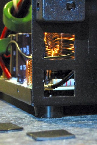 At this point, you will need 4 pairs of Anderson PowerPoles:
Four pairs of PowerPoles:
At this point, you will need 4 pairs of Anderson PowerPoles:
Four pairs of PowerPoles: 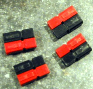 Looking in the power supply, you will notice a short black wire connecting the black setscrew connector to a mounting screw for the circuit board. Remove the circuit board mounting screw to free up the black wire. It is much easier to install the powerpoles when you can move this wire out of the way.
Temporarily remove chassis ground wire for some work space:
Looking in the power supply, you will notice a short black wire connecting the black setscrew connector to a mounting screw for the circuit board. Remove the circuit board mounting screw to free up the black wire. It is much easier to install the powerpoles when you can move this wire out of the way.
Temporarily remove chassis ground wire for some work space: 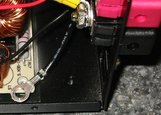 Starting with the lower hole, insert the first set of powerpoles. If you start with the upper hole, the powerpoles will be in the way when you go to install the lower hole powerpoles. I don't think it really matters which way you install the connectors (black on top, red on top, whatever), as long as you put all four pairs in the same way. With a little work, you can snap the first pair of connectors into the hole. You want the edge of the metal hole resting in the half-circle indentations on the sides of the connectors. If you have trouble getting the powerpoles in place, try sliding one pole partway back, so you can set one pole in place, then slide the other up into place.
First pair of powerpoles in place:
First pair of powerpoles in place:
Starting with the lower hole, insert the first set of powerpoles. If you start with the upper hole, the powerpoles will be in the way when you go to install the lower hole powerpoles. I don't think it really matters which way you install the connectors (black on top, red on top, whatever), as long as you put all four pairs in the same way. With a little work, you can snap the first pair of connectors into the hole. You want the edge of the metal hole resting in the half-circle indentations on the sides of the connectors. If you have trouble getting the powerpoles in place, try sliding one pole partway back, so you can set one pole in place, then slide the other up into place.
First pair of powerpoles in place:
First pair of powerpoles in place: 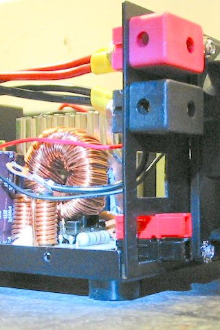 If you look closely, you can see how the half-circle indentation on the side of the powerpoles is sitting on the metal edges of the hole.
Next, take one of the metal knockouts (you saved them, right?), and place it edgewise in the hole, up against the powerpoles. This acts as a spacer to keep the powerpoles from sliding back-and-forth in the hole, and to add a little clearance between the connector pairs to make it easier to plug in cables. Be sure to set the knockout far enough back that it won't interfere with connecting powerpoles.
Using a knocked out knockout as a spacer:
If you look closely, you can see how the half-circle indentation on the side of the powerpoles is sitting on the metal edges of the hole.
Next, take one of the metal knockouts (you saved them, right?), and place it edgewise in the hole, up against the powerpoles. This acts as a spacer to keep the powerpoles from sliding back-and-forth in the hole, and to add a little clearance between the connector pairs to make it easier to plug in cables. Be sure to set the knockout far enough back that it won't interfere with connecting powerpoles.
Using a knocked out knockout as a spacer: 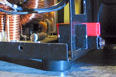 Finally, insert the second pair of powerpoles. This picture shows one pole offset to make it easier to get the connectors in the hole:
Inserting second pair of powerpoles:
Finally, insert the second pair of powerpoles. This picture shows one pole offset to make it easier to get the connectors in the hole:
Inserting second pair of powerpoles: 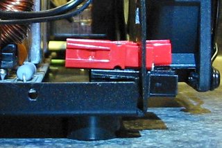 Once the two pairs of powerpoles are in place I put a zip tie around them to lock everything down. Make sure you've got the powerpoles fully snapped together and lined up. Later, I also added a little glue, but I don't have a good picture of that.
First set of powerpoles installed in lower hole:
Once the two pairs of powerpoles are in place I put a zip tie around them to lock everything down. Make sure you've got the powerpoles fully snapped together and lined up. Later, I also added a little glue, but I don't have a good picture of that.
First set of powerpoles installed in lower hole: 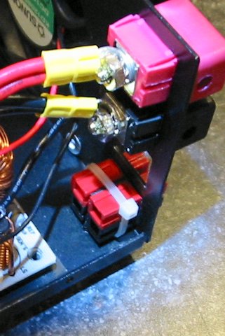 Now that you've got the lower set in, repeat the process to to install the upper set. Here is a picture showing both sets installed:
All powerpoles installed:
Now that you've got the lower set in, repeat the process to to install the upper set. Here is a picture showing both sets installed:
All powerpoles installed: 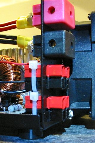 Next you need to prepare some jumpers to get power to the powerpoles. Since I might be pulling as much as 15 or 20 amps through one of the powerpole connections, I made sure to use 12 gauge wire. I made the jumpers about 6 inches long. They could be a little shorter, but I've found it a little easier to install them when they are about 6 inches. Make four jumpers - a ring connector at one end, connected to two wires, with the powerpole pins on the ends:
Jumpers for connecting the powerpoles:
Next you need to prepare some jumpers to get power to the powerpoles. Since I might be pulling as much as 15 or 20 amps through one of the powerpole connections, I made sure to use 12 gauge wire. I made the jumpers about 6 inches long. They could be a little shorter, but I've found it a little easier to install them when they are about 6 inches. Make four jumpers - a ring connector at one end, connected to two wires, with the powerpole pins on the ends:
Jumpers for connecting the powerpoles: 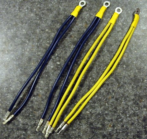 At this point, you will want to remove the red and black wires from the back of the set screw connectors. This is also where you will end up connecting your new jumpers. Note that Astron puts some threadlock compound on the nuts on the back of the setscrew connectors, so they may require a little force to remove. Just be careful not to break or strip anything.
Starting with the bottom set of powerpoles, insert the pin ends of the jumpers. Again, pay attention to the order you do this, so you start with the furthest back powerpoles, so you don't get in your own way. Also, be careful not to get your red and black (or blue and yellow, as in the pictures) jumpers twisted around or through each other.
And of course, make sure you are keeping your positives and negatives correct. You really don't want to cross wire anything.
Installing first jumpers:
At this point, you will want to remove the red and black wires from the back of the set screw connectors. This is also where you will end up connecting your new jumpers. Note that Astron puts some threadlock compound on the nuts on the back of the setscrew connectors, so they may require a little force to remove. Just be careful not to break or strip anything.
Starting with the bottom set of powerpoles, insert the pin ends of the jumpers. Again, pay attention to the order you do this, so you start with the furthest back powerpoles, so you don't get in your own way. Also, be careful not to get your red and black (or blue and yellow, as in the pictures) jumpers twisted around or through each other.
And of course, make sure you are keeping your positives and negatives correct. You really don't want to cross wire anything.
Installing first jumpers: 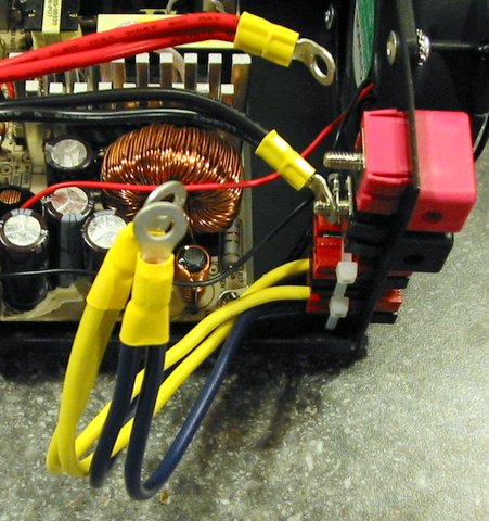 Once you've installed all four jumpers, it is time to connect the black (or blue) wires to the back of the black setscrew connector. NOTE: Right now is a really good time to reattach that short black jumper you disconnected a few steps back. When you tighten the screw, make sure the ring connector on the circuit board end of short black wire is not touching anything, like the lead of that big resistor right next to it.
Now, bend the black (or blue) wires around so you can get the ring connectors onto the screw on the back of the black setscrew connector. All of the things you need to fit on this screw will pretty much take up all the room available, so you may have to work things around a little bit, or flip over a ring connector to get everything to fit. When everything is in place, it should be in this order:
NUT - ASTRON SUPPLY LEAD - POWERPOLE JUMPERS - SHORT BLACK WIRE TO CIRCUIT BOARD - SETSCREW CONNECTOR
This would be a good time to make sure you haven't accidentally cross wired a connector. You don't want to connect the negative to positive.
Route the excess wire around so it isn't rubbing up against anything, particularly the aluminum heatsink. Make sure it doesn't interfere with the fan, or airflow towards the heatsink.
First set of jumpers installed and connected:
Once you've installed all four jumpers, it is time to connect the black (or blue) wires to the back of the black setscrew connector. NOTE: Right now is a really good time to reattach that short black jumper you disconnected a few steps back. When you tighten the screw, make sure the ring connector on the circuit board end of short black wire is not touching anything, like the lead of that big resistor right next to it.
Now, bend the black (or blue) wires around so you can get the ring connectors onto the screw on the back of the black setscrew connector. All of the things you need to fit on this screw will pretty much take up all the room available, so you may have to work things around a little bit, or flip over a ring connector to get everything to fit. When everything is in place, it should be in this order:
NUT - ASTRON SUPPLY LEAD - POWERPOLE JUMPERS - SHORT BLACK WIRE TO CIRCUIT BOARD - SETSCREW CONNECTOR
This would be a good time to make sure you haven't accidentally cross wired a connector. You don't want to connect the negative to positive.
Route the excess wire around so it isn't rubbing up against anything, particularly the aluminum heatsink. Make sure it doesn't interfere with the fan, or airflow towards the heatsink.
First set of jumpers installed and connected: 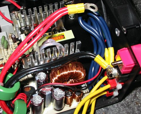 Once you've got the first set of jumpers connected, hook up the second set of jumpers. Again, double check that you haven't cross wired anything. The order on the back of the red setscrew connector should be:
NUT - ASTRON SUPPLY LEAD - POWERPOLE JUMPERS - SETSCREW CONNECTOR
Also, make sure that you don't have any of the ring connectors turned upwards, where they could get in the way of putting the power supply case back together.
Here is what it looks like when it is all done. The jumper wires don't necessarily have to curve back the way they do in this picture. In one of the other conversions I've done, they ended up more to the left, over the capacitors.
All jumpers connected:
Once you've got the first set of jumpers connected, hook up the second set of jumpers. Again, double check that you haven't cross wired anything. The order on the back of the red setscrew connector should be:
NUT - ASTRON SUPPLY LEAD - POWERPOLE JUMPERS - SETSCREW CONNECTOR
Also, make sure that you don't have any of the ring connectors turned upwards, where they could get in the way of putting the power supply case back together.
Here is what it looks like when it is all done. The jumper wires don't necessarily have to curve back the way they do in this picture. In one of the other conversions I've done, they ended up more to the left, over the capacitors.
All jumpers connected: 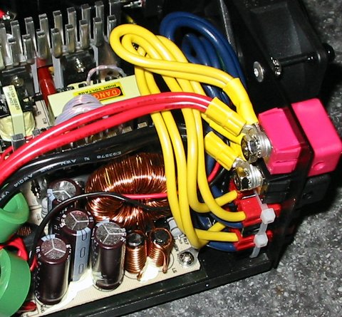 Before you put the case back together, check that:
- You reconnected the short black jumper wire to the circuit board.
- You maintained polarity on your connectors.